ALSA AXI DMA module
In our project, audio coming from Bluetooth will need to be send to the PL for further processing and mixing with analogs input(s). We will use the Xilinx AXI DMA IP block for this, which will register some DMA channels in the PS that we can use (the Xilinx AXI DMA kernel driver handles this).
Vivado
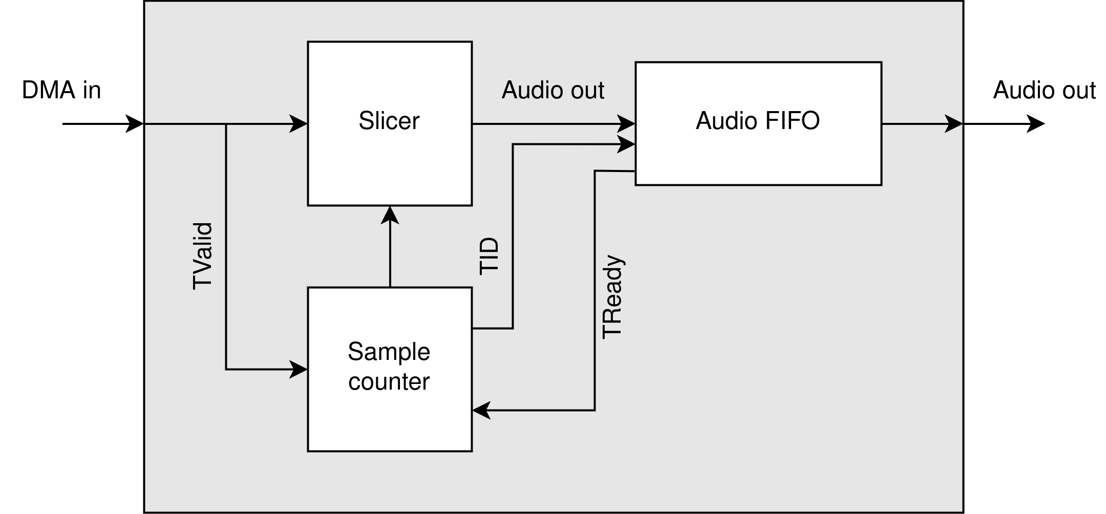
On the PL side of things, we first had to add the DMA IP provided by Xilinx. This module takes care of communication to the DRAM and provides us with an AXI data stream. The size of a DMA word on this stream is 128 bit, in which 4 24 bit samples are stored. We made a small arbiter which is responsible for taking in the DMA word, and splitting it into an AXI audio stream.
Limitations
Due to some time limitations, we do not take advantage of the full throughput of the DMA stream. This is due to some time limitations and suboptimal planning on the PL side, since we did not know what it would take to process the DMA stream.
Schematic
Custom Kernel Driver
Creating the Module
To enable sound samples to be send to the PL, we developed a custom kernel module that will register a new virtual soundcard and PCM device with the system. This module will work together with ALSA to process audio in the PS and send the samples to the PL via DMA.
We created the custom module using the petalinux-create command within our PetaLinux project environment:
This command generates a new module located at:
/project-spec/meta-user/recipes-modules/alsa-axi-dma
This directory contains a template for a PetaLinux kernel module, including the following files:
alsa-axi-dma.bb– BitBake recipe for building the module.alsa-axi-dma.c– The C source file for the driver.Makefile– Build instructions for the kernel module.
ALSA background
Before we go into the module source code, we will go through a little background information about the ALSA architecture. Writing an ALSA device driver is not very common, so the amount of information on the internet is sparse. There are however a few resources which provide enough information to start writing an ALSA driver. A good starting point was a presentation named ALSA: Writing the soundcard driver by Ivan Orlov which outlined the basics of a sound card driver. We will use some snippets from the presentation in this documentation by way of illustration.
Basic structure
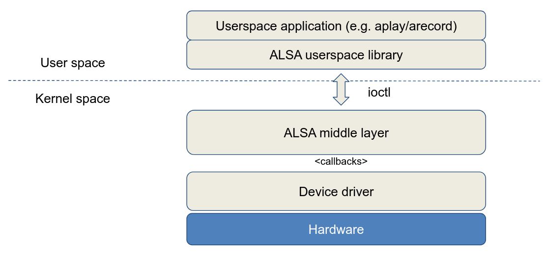
The bigger picture of the ALSA environment is outlined in the image below. An application, such as aplay, uses the ALSA userspace library and communicates with the ALSA middle layer via ioctl calls. This ALSA middle layer manages everything about the sound stream: both the device driver and the application listen to this middle layer.
The middle layer communicates with the driver via so-called callback functions that must be defined in the driver. Thus, when registering the sound card in the system, the driver will also have to provide these callbacks so that ALSA can use them.
Callback functions
When writing the driver, we can choose from a large number of callbacks to communicate with the higher layers. However, there are standard implementations for most callbacks, so we will only need to re-implement a limited amount of callbacks in the driver according to the needs.
The main callbacks that are almost always implemented in a driver are listed below:
- open: called when the substream is opened for capture/playback, this callback has to set up the constraints of the PCM device (sample rate, sample format, channels, accepted buffer and period sizes)
- close: called when the substream is closed, has to free all runtime private data
- hw_params: called when the application sets the hardware settings (buffer and period size, format, rate), as long as they are accepted by the driver (see open callback). Buffers are allocated and hardware is set up in this callback.
- hw_free: called just before the close callback to free the allocated resources
- prepare: called every time snd_pcm_prepare is called in the ALSA middle layer, mostly after underruns
- trigger: called when an event in the stream occurs, possible events are SNDRV_PCM_TRIGGER_STOP, SNDRV_PCM_TRIGGER_START, SNDRV_PCM_TRIGGER_PAUSE_PUSH, SNDRV_PCM_TRIGGER_SUSPEND, etc
- pointer: called and used by the ALSA middle layer to get the current hardware buffer pointer value, returns the value in frames
Some drivers also implement the ioctl callback which allows a redefinition of some of the PCM read ioctls, but in most cases we can stick with the default implementation in the ALSA middle layer.
Important note: some callbacks are atomic, which means that they cannot be interrupted. Consequently, no mutexes, spin-locks or other locking mechanisms may be used in these calls: due to the atomic nature, race conditions will never exist in this callback. The three atomic callbacks are trigger, pointer and ack.
Periods and Buffers
Another important concept in the ALSA achitecture are buffers and periods. Before we continue to discuss these concepts, it is important to note that from now on we are going to work mainly with frames instead of bytes. A frame contains 2 audio samples (in the case of stereo or 2-channel audio), which in 24-bit audio amounts to a frame of 6 bytes. However, there are several ways to define frames, 24-bit audio, for example, can also be divided into frames of 8 bytes with each sample being 1 byte zero-padded. These properties are also among the hardware parameters that must be defined in the driver and negotiated with the application.
In general, there are 2 buffers: the hardware and software buffer. The hardware buffer contains frames which are processed by the hardware. The software buffer contains frames which are processed by the application. These buffers are ringbuffers: once the buffer is full, data is resumed at the beginning of the buffer. This concept will be important for the application and hardware pointer.
In the driver, we will copy the data from the software to the hardware buffer in small chunks called periods. Every time the hardware processes a period it notifies the ALSA middle layer. The size of a period can vary within substreams and is set for every substream in the hw_params callback. It is possible to define a period size min and max in the driver to have a bit more control over the negotiated period size.
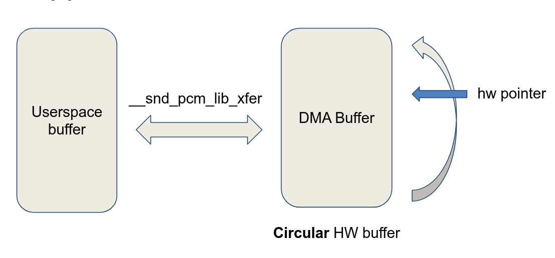
The ALSA middle layer contains an application pointer indicating up to where in the software buffer the application has written data. The driver contains a hardware pointer indicating up to where in the hardware buffer the hardware has processed data. Every time the driver processes a period of data, it notifies ALSA and updates its hardware pointer. Usually ALSA will call the pointer callback after receiving the period elapsed signal to obtain the current hardware pointer. When updating the hardware pointer in the driver, it is important to keep the concept of ringbuffers in mind.
Underruns
An underrun occurs in playback when the application doesn't write data frequently enough so that the PCM device starts starving for new data. At first this may sound a rather fuzzy concept, but when reviewing the source code of the driver it'll become immediately clear why this situation is highly unwanted. Specifically, an underrun will occur as soon as the difference between the application and hardware pointer is less than 1 period. The driver will then notify the ALSA middle layer of the existing XRUN (underrun) and stop the stream for a moment. It is then up to ALSA to recover from this underrun, in most situations by just resetting the buffers and preparing the hardware by using the prepare callback again.
The opposite of an underrun occurs in the capture process: an overrun. Since we will not be doing capture in this project, this will not be discussed further.
Final Words
The above concepts form the basis of the ALSA architecture. However, it is important to note that there are several other concepts within ALSA: different substreams, capture mode, controls, timers, etc. More information about these concepts can be found in the used references for this documentation below.
Driver Source Code
Now that we know a bit about ALSA, we can go through the module we created. The hardware parameters of our driver are defined as a snd_pcm_hardware struct at the top of the module:
static struct snd_pcm_hardware dma_pcm_hardware = {
    .info = SNDRV_PCM_INFO_INTERLEAVED | SNDRV_PCM_INFO_BLOCK_TRANSFER,
    .formats = SNDRV_PCM_FMTBIT_S24_3LE | SNDRV_PCM_FMTBIT_S24_LE,
    .rates = SNDRV_PCM_RATE_48000,
    .rate_min = 48000,
    .rate_max = 48000,
    .channels_min = 2,
    .channels_max = 2,
    .buffer_bytes_max = AUDIO_BUFFER_SIZE,
    .period_bytes_min = 4096,
    .period_bytes_max = 16384,
    .periods_min = 2,
    .periods_max = 8,
};
The most important takeaway here is that our virtual soundcard will only support 24-bit 48kHz audio and has a max buffer size of 256 kB. This means that the driver will introduce a maximum latency of 900ms when the negotiated buffer size equals the max buffer size. It is important to notice that this isn't the final latency that will be observed when listening to the audio: other factors like the Bluetooth connection also introduce extra latency. In our project, we decided that when listening to music, latency isn't the biggest concern like it is when gaming or watching media content. The used high-quality codec aptX-HD has a max bitrate of almost 560 kbit/s which means the Bluetooth connection can become a bit unstable. To keep the audio stream smooth and compensate for possible unstabilities in the stream, a rather big hardware buffer can be used.
In the driver, we created a function write_to_buffer() which will take a period of data from the software buffer, zero pad the data so that it's ready to be processed in the PL, writes it to the hardware buffer and starts the DMA so the data is being send to the PL. When this transfer is done, an interrupt is generated which will schedule work in a work queue and notify ALSA that a period has been elapsed. Because the write_to_buffer() function contains mutex locks for safe access to the DMA buffer, we can't execute it from within the interrupt subroutine which is atomic. This is why the work handler for the scheduled work in the interrupt will take care of this.
Data is writtin into the DMA buffer in the following format:
64-bit word in memory: < L1, L2, L3, R1, R2, R3, 0, 0 >
where every sample is 3 byte (24 bit).
Driver Compilation
Usage
References
As mentioned earlier, the resources about writing an ALSA driver are very scarce. The resources below helped us tremendously towards creating the driver we have now. We hope this documentation and the written ALSA driver will add to the scarce resources and help others.