HDL
Filters and audio effects
We have converted the filters and audio effects tested in MATLAB and Simulink to VHDL code by using small parts of the code generated by the HDL coder from MATLAB.
All VHDL modules are designed to support AXI Streaming for processing audio samples and include AXI Memory-Mapped (AXI-MM) interfaces for controlling module settings. Most modules are compatible with Time-Division Multiplexing (TDM), enabling dynamic behavior based on the audio source currently passing through the module. For example, one module can attenuate the volume of a specific frequency band for one audio source while simultaneously amplifying a different frequency band for another source. The '_tdm' suffix in the filename indicates that the module supports Time-Division Multiplexing (TDM).
All modules feature consistent input and output ports, allowing for seamless interconnection between them:
port(
    -- clocking
    clk : in std_logic;
    axi_clk : in std_logic; -- (Sometimes optional)

    -- axi mm
    axi_in_mm : in t_axi4_mm_filter / t_axi4_mm_echo / t_axi4_mm_ring_mod / t_axi4_mm_saturation / t_axi4_mm_band_volume / t_axi4_mm_volume; -- (Depending of the module)

    -- axi inputs
    axi_in_fwd : in t_axi4_audio_fwd;
    axi_in_bwd : out t_axi4_audio_bwd;

    -- axi outputs
    axi_out_fwd : out t_axi4_audio_fwd;
    axi_out_bwd : in t_axi4_audio_bwd

);
biquad_tdm
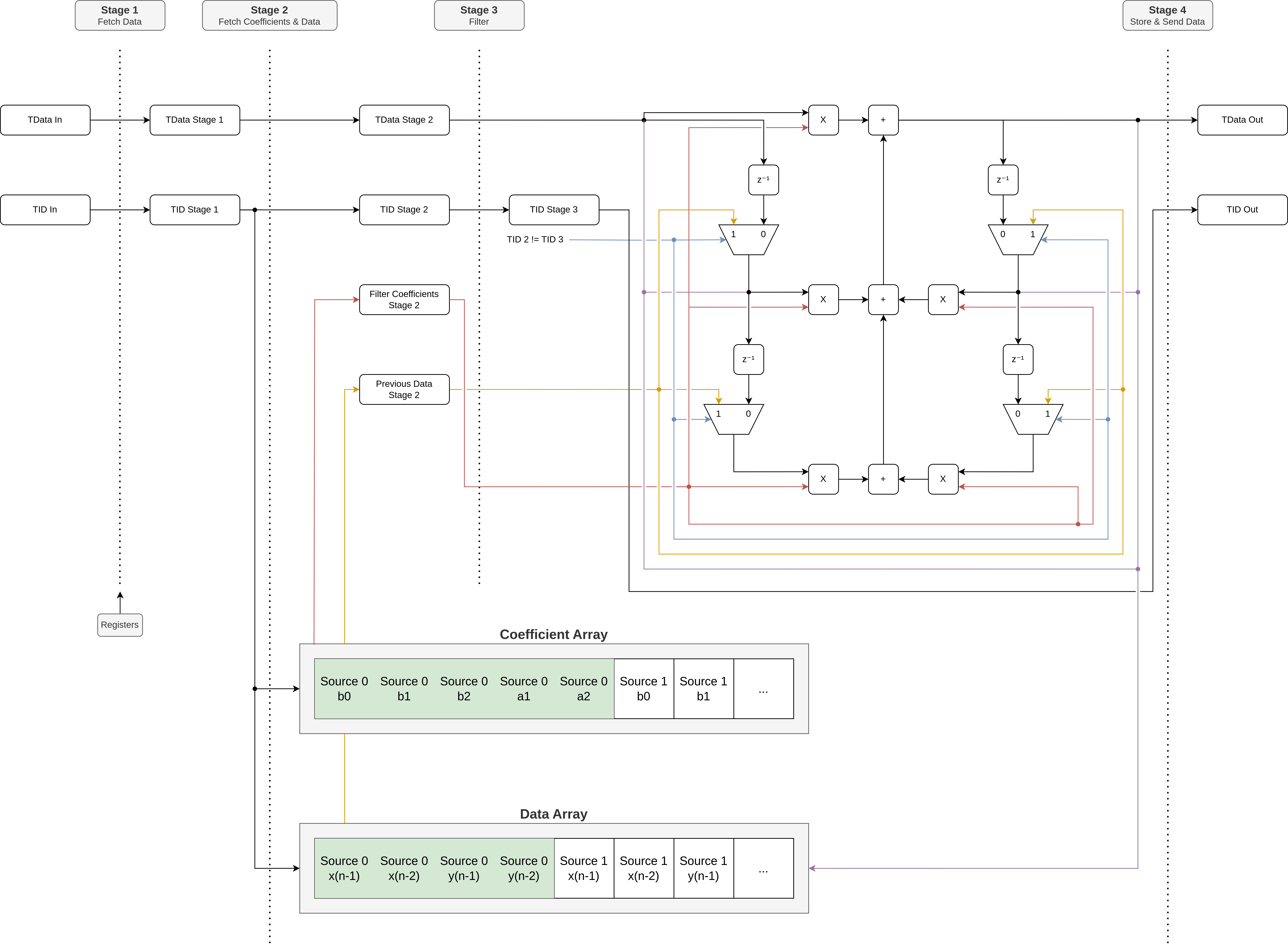
This module implements the Direct Form 1 Digital Biquad Filter. It can thus be used to make a second order section of a low-shelf, band-shelf, high-shelf, low-pass or high-pass filter.
It uses the following record for interfacing with AXI MM :
type t_axi4_mm_filter is record
    b0 : sfixed(3 downto -23);
    b1 : sfixed(3 downto -23);
    b2 : sfixed(3 downto -23);
    a1 : sfixed(3 downto -23);
    a2 : sfixed(3 downto -23);
    channel_adress : std_logic_vector(c_ID_width - 1 downto 0);
    strobe : std_logic;
end record t_axi4_mm_filter;

constant axi4_mm_filter_inactive : t_axi4_mm_filter := (
    b0 => to_sfixed(1.0, 3, -23),
    b1 => to_sfixed(1.0, 3, -23),
    b2 => to_sfixed(1.0, 3, -23),
    a1 => to_sfixed(1.0, 3, -23),
    a2 => to_sfixed(1.0, 3, -23),
    channel_adress => (others => '0'),
    strobe => '0'
);
a1, a2, b0, b1 and b2 signals are the coefficients for a normalized biquad filter and the channel_adress indicates for which source.
The filter coefficients (a1, a2, b0, b1 and b2) for a specific channel_address must be updated simultaneously. When the strobe signal is high, all coefficients for the specified channel_address are loaded into the filter concurrently, ensuring synchronized updates.
This is the block diagram of the implementation of the biquad in VHDL:
echo_tdm
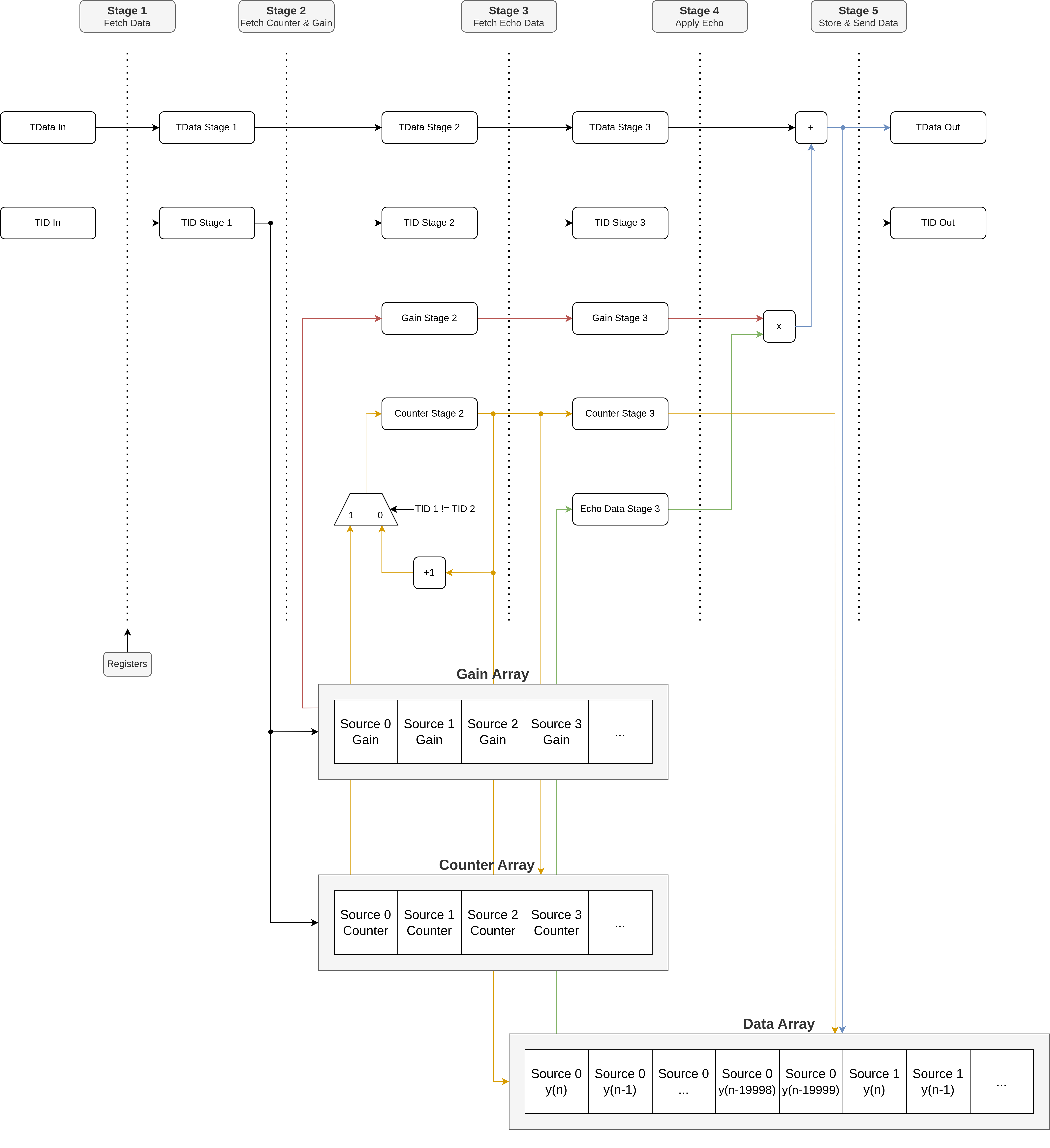
This module implements the echo audio effect.
It uses the following record for interfacing with AXI MM :
type t_axi4_mm_echo is record
    channel_value : sfixed(0 downto -23);
    channel_adress : std_logic_vector(c_ID_width - 1 downto 0);
    strobe : std_logic;
end record t_axi4_mm_echo;

constant axi4_mm_echo_inactive : t_axi4_mm_echo := (
    channel_value =>to_sfixed(0.0, 0, -23),
    channel_adress => (others => '0'),
    strobe => '0'
);
The channel_value is the amount of echo you want (between 0 and 1) and the channel_adress indicates for which source.
To ensure the correct channel_value is updated, this module employs a strobe signal. This mechanism prevents issues where the channel_address arrives later than the channel_value, which could otherwise result in the internal channel_value of the previous channel_address being updated with the channel_value intended for the current channel_address.
This is the block diagram of the implementation of the echo in VHDL:
saturation_tdm
This module implements the saturation audio effect.
It uses the following record for interfacing with AXI MM :
type t_axi4_mm_saturation is record
    channel_value : sfixed(3 downto -23);
    channel_adress : std_logic_vector(c_ID_width - 1 downto 0);
    strobe : std_logic;
end record t_axi4_mm_saturation;

constant axi4_mm_saturation_inactive : t_axi4_mm_saturation := (
    channel_value =>to_sfixed(1.0, 3, -23),
    channel_adress => (others => '0'),
    strobe => '0'
);
The channel_value is the amount of gain you want (between 1 and 50V/V) and the channel_adress indicates for which source.
This module also uses a strobe signal for the same reasons as the echo_tdm module.
volume
This module attenuates the volume of every source that passes through it.
It uses the following record for interfacing with AXI MM :
type t_axi4_mm_volume is record
    channel_value : sfixed(0 downto -23);
end record t_axi4_mm_volume;

constant axi4_mm_volume_inactive : t_axi4_mm_volume := (
    channel_value =>to_sfixed(0.5012, 0, -23)  -- -6dB
);
The channel_value is the amount of attentuation you want (between 1 and 0V/V).
When a new channel_value is provided, the internal value is updated immediately.
band_volume (same as volume but supports TDM)
This module amplifies/attenuates the volume of every source that passes through it.
It uses the following record for interfacing with AXI MM :
type t_axi4_mm_band_volume is record
    channel_value : sfixed(1 downto -23);
    channel_adress : std_logic_vector(c_ID_width - 1 downto 0);
    strobe : std_logic;
end record t_axi4_mm_band_volume;

constant axi4_mm_band_volume_inactive : t_axi4_mm_band_volume := (
    channel_value =>to_sfixed(1.0, 1, -23),
    channel_adress => (others => '0'),
    strobe => '0'
);
The channel_value is the amount of gain you want (between 0.0501
and 2V/V) and the channel_adress indicates for which source.
This module also uses a strobe signal for the same reasons as the echo_tdm module.
ring_modulator
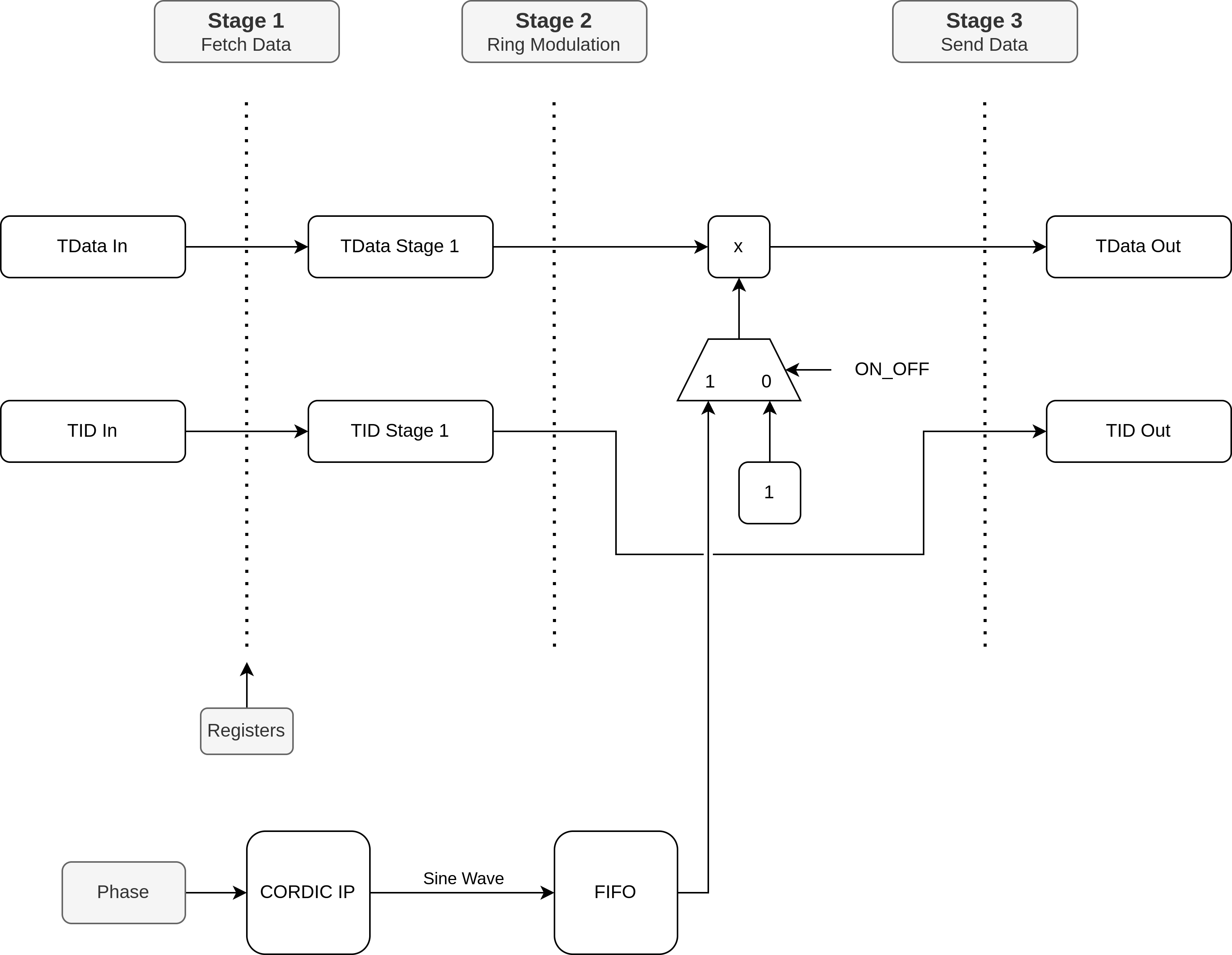
This module implements the ring modulator audio effect. This module internally uses the LogiCORE™ CORDIC IP to generate a cosine wave that it will use as modulator for the ring modulation effect.
It uses the following record for interfacing with AXI MM :
type t_axi4_mm_ring_mod is record
    on_off : std_logic;
    phase_inc : integer;
end record t_axi4_mm_ring_mod;

constant axi4_mm_ring_mod_inactive : t_axi4_mm_ring_mod := (
    on_off => '0',
    phase_inc => 256
);
the on_off signal is for enabling/disabling the ring modulator effect and the phase_inc is for adjusting the speed of the effect.
When a new on_off or phase_inc is provided, the internal value is updated immediately.
This is the block diagram of the implementation of the ring modulator in VHDL:
low_pass
This module implements a dedicated low-pass filter, essentially a specialized version of the biquad_tdm module with fixed filter coefficients. It applies a low-pass filter with a cutoff frequency of 23 kHz to all signals passing through it. Since the filter coefficients are hardcoded, there is no need for a connection to the Processing System (PS) to update the module.
Wrapper
The filters_effects_wrapper module contains the whole filter and audio effects pipeline (except for the ring_modulator and low_pass filter as these modules are placed at another location in the whole audio processing pipeline).
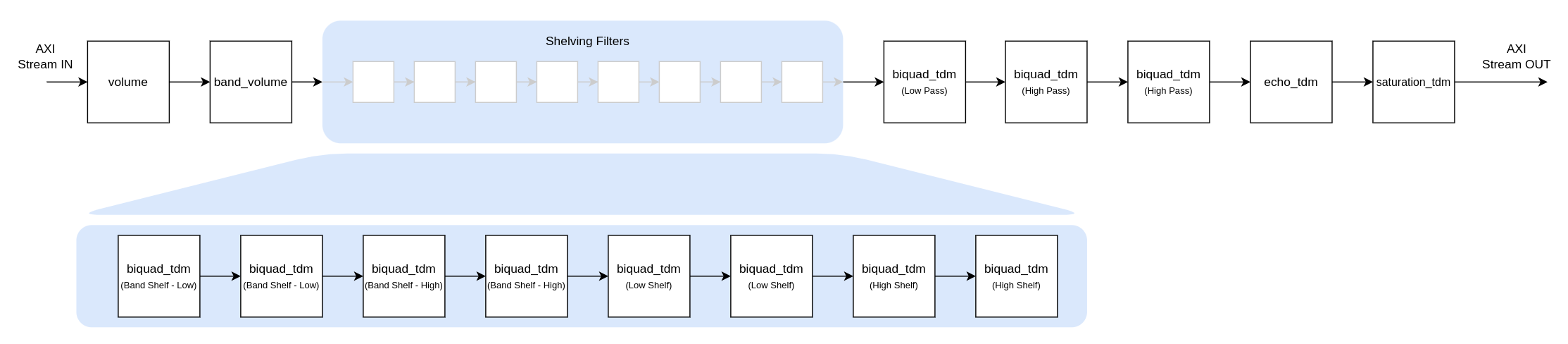
The audio signal first passes through a volume module that attentuates the volume of every source with (probably) -6dB.
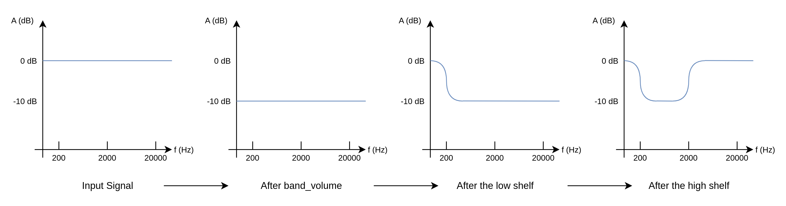
Then it passes through the band_volume module which is part of the band shelf filter. The band shelf filter contains 4 biquad_tdm modules, two of them act as a low shelf filter and the other two act as a high shelf filter. So, how does the band shelving filter work? If you for example want an attenuation of -10dB, you first pass the signal through the band_volume module which will lower the volume of the full bandwidth of the signal with -10dB, then the low and high shelving filters will amplify the low and high frequencies again with +10dB so there will not be any change in volume in those frequency ranges.
This is what the complete band-shelf filter looks like:
Then the signal passes through the low and high shelving filters, which both use 2 biqued_tdm modules, to control the gain of the low and high frequency bandwidth.
Then the signal will be modified by the low and high pass filters, which are made by respectivelly 1 and 2 biquad_tdm modules.
After passing through all the filters, the signal will pass through the audio effects. It first passs through the echo_tdm and afterwards through the saturation_tdm.