HDL mixer
To mix channels together, we of course need a mixing module. This is our attempt to do this.
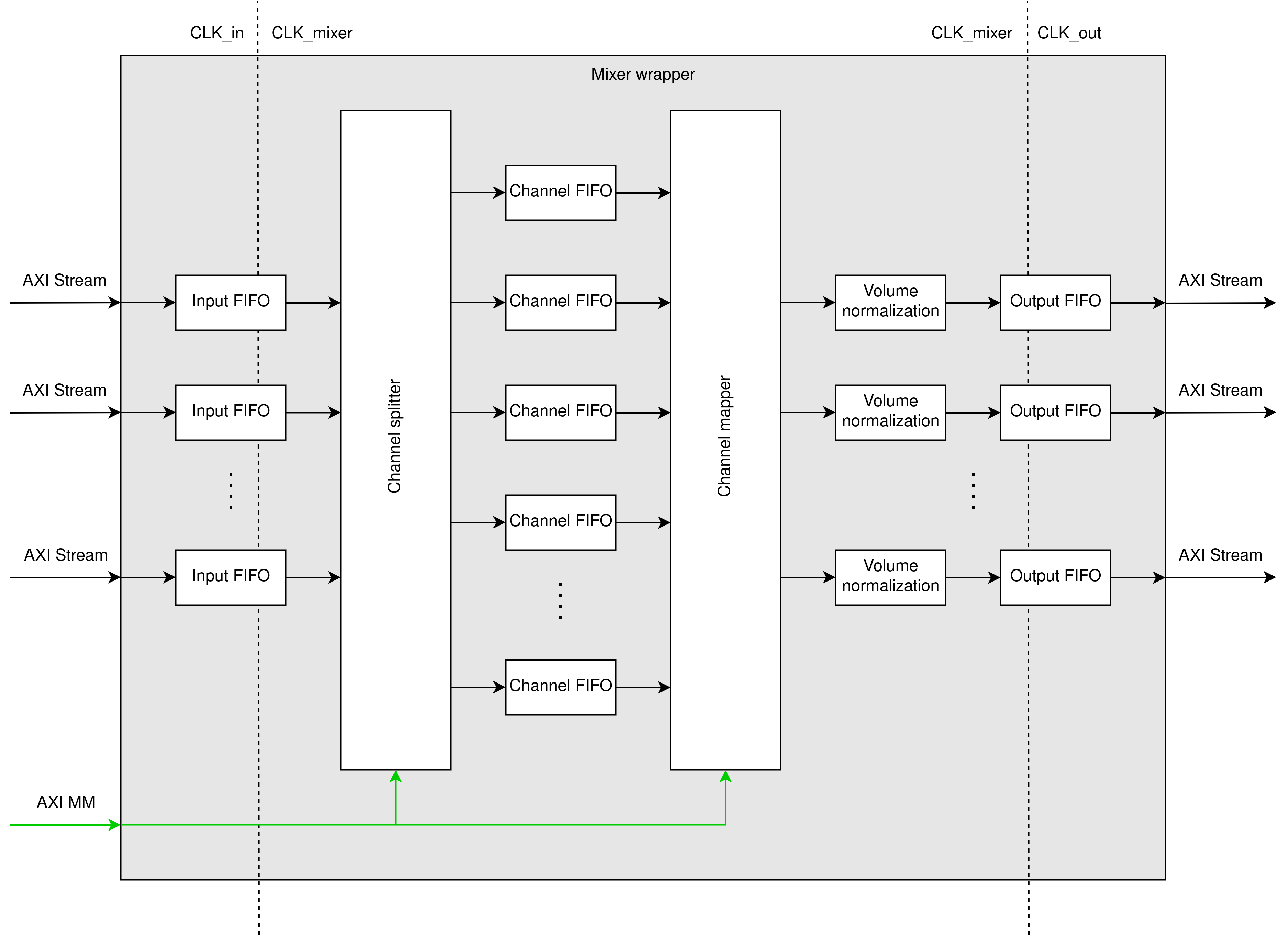
Schematic:
Features
Due to a lack of time, we did not implement the full mixer, but rather an application specific version because this made development and testing faster.
- Can run at about 250 MHz
- Mix left dma and analog together
- Mix right dma and analog together
- Merge the mixed streams into one
- Use of the
fixed_pkgVHDL standard for proper fixed point number handling - Fully AXI stream compliant
- Volume normalization when mixing dma and analog
- Bypass when there is no DMA present
- Area usage: 738 LUT, 1220 FF, 4 BRAM, 1 DSP
Components
As can be seen in the schematic, the mixer is made up of a lot of different components. The FIFO's are fairly self-explanatory, and are used so ubiquitously that they have their own documentation page. Everything else which has significance is described below.
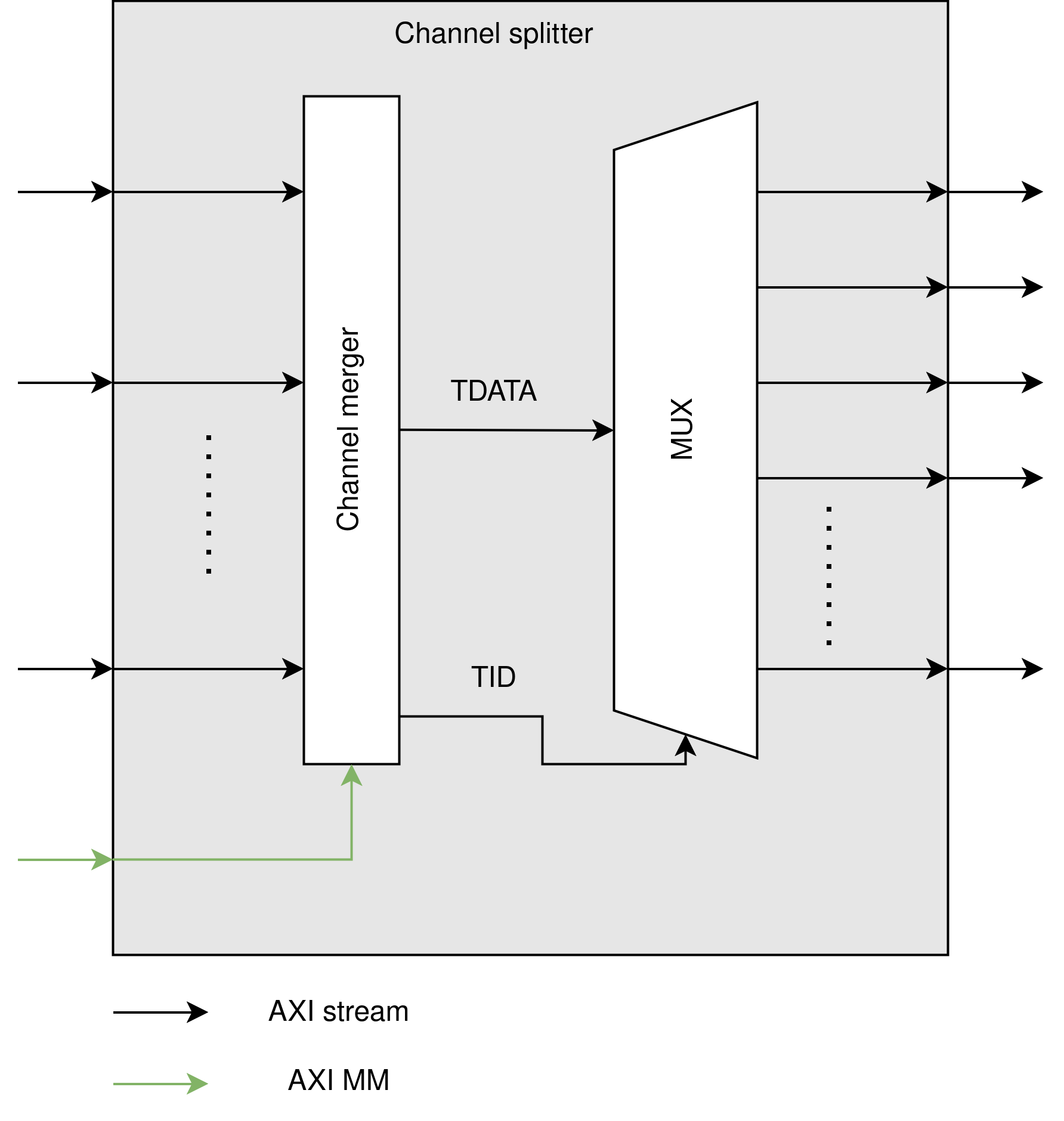
Channel splitter
The channel splitter takes in an array of TDM AXI streams and splits them into their individual components. To do this, we use a channel merger to get every channel into one stream, and then split them out into new AXI busses based on their TID:
The overall structure takes the following shape:
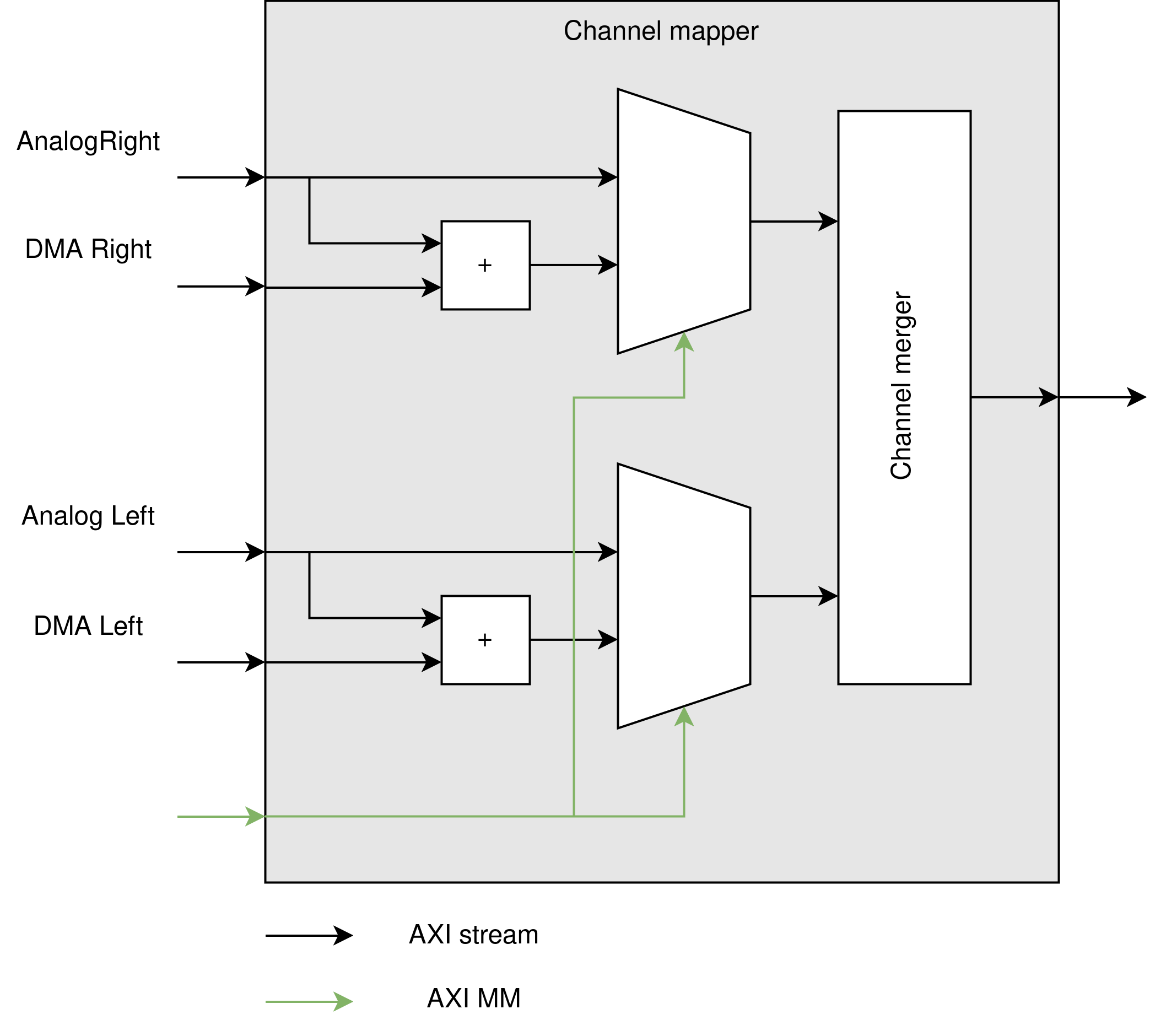
Channel mapper
Unlike other modules in this list, the channel mapper is not generic, but specific to our use case. Unfortunately, there was no time to make a generic version left, so we quickly made an implementation of the following schematic. It adds analog and DMA when told to do so by the PS, otherwise it bypasses the addition. Then the left and right channels get merged so they can be sent to I2S modules (after final volume adjustment).
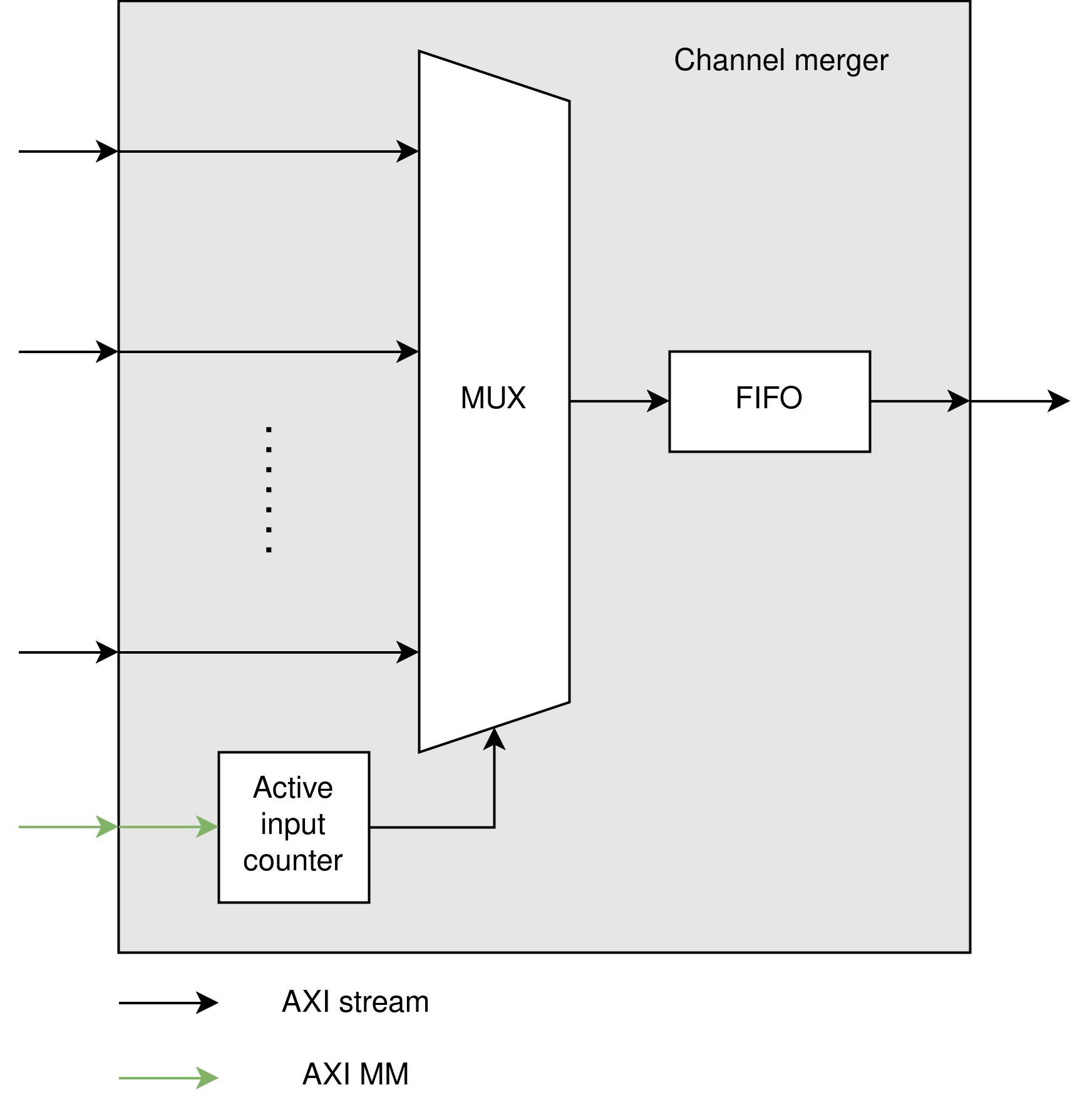
Channel merger
The channel merger is not only used here, but as can be seen in the overall pipeline, it is also used for merging analog and DMA streams before filtering and effects. We use some AXI MM in the form of AXI LITE to control which of the input channels can become the active input on the internal mux. Then, we loop over each active input to move the data from the incoming busses to the FIFO.
The overall structure takes the following shape:
Volume normalization
This is just a volume control unit, which is set to attenuate 3db if DMA is active, and no attenuation when only using the analog input.