Convert MIDI signals to the AXI Memory-Mapped Interface
Receiving the MIDI signals in Python
To receive the MIDI signals, we use python-rtmidi. This is a Python library for working with realtime MIDI input and output.
To be able to work with python-rtmidi, we need to install the following package:
The following Python code was written to receive the MIDI messages:
import rtmidi
import time

port_name = 'Reloop BeatMix:Reloop BeatMix MIDI 1 24:0' # Replace with your actual MIDI device port name.

def main():
    try:
        # Initialize the MIDI input
        midi_in = rtmidi.MidiIn()

        # List available ports and find the port index for the given name
        available_ports = midi_in.get_ports()

        if port_name in available_ports:
            port_index = available_ports.index(port_name)
            midi_in.open_port(port_index)
            # Callback function for incoming messages
            def midi_callback(message, data):
                print(f"{message[0]}", flush=True)

            # Set the callback function to process incoming messages
            midi_in.set_callback(midi_callback)

            # Keep the program running to listen for MIDI messages
            while True:
                time.sleep(0.01)
        else:
            print(f"Port '{port_name}' not found. Available ports: {available_ports}")
    except KeyboardInterrupt:
        print("Stopped listening.")
    except Exception as e:
        print(f"Error: {e}")

if __name__ == "__main__":
    main()
MIDI signals consist of 3 bytes of data: one status byte and two data bytes. This Python script monitors the specified port and prints the MIDI messages in their decimal form in the following format: [Status Byte, Data Byte 1, Data Byte 2].
To view all available MIDI input ports, you can execute the following Python code:
import rtmidi

# Create an input MIDI stream
midi_in = rtmidi.MidiIn()

# List available input ports
available_ports = midi_in.get_ports()
print("Available MIDI input ports:")
for port in available_ports:
    print(f" - {port}")
Writing the MIDI signals to the AXI Lite in C
During the development of the MIDI code, we initially stored MIDI signals in a binary format in a destination file of our choice. Each line of the file contained a MIDI message (e.g., 0b10010000 0b00110000 0b01000000). The following C code reads the MIDI data, received via the python-rtmidi library, from the specified destination file. It processes the strings into 32-bit words and writes them to the mapped AXI Lite memory. For each MIDI message, the memory offset is incremented by 4 bytes, ensuring that each message is written correctly in a different register and can be validated afterwards.
This code is intended as a development prototype and will not be part of the final project, but will serve as a starting point of our C++ code. When executing the code, the destination file's filename must be provided as a parameter.
#include <stdio.h>
#include <stdlib.h>
#include <string.h>
#include <stdint.h>
#include <fcntl.h>
#include <unistd.h>
#include <sys/mman.h>
#include <time.h>

#define AXI_BASE_ADDR 0xA0040000    // AXI base address
#define AXI_START_OFFSET 0x00       // Starting offset
#define AXI_OFFSET_SIZE 0x04       //  Offset size
#define MMAP_SIZE 0x10000           // Size of memory to map (64KB in this case)

void* axi_base_addr = NULL; // Will be initialized via mmap

// Function to parse a binary string (e.g., "0b10010000") into a uint8_t
uint8_t parse_binary(const char *binary_str) {
    return (uint8_t)strtol(binary_str + 2, NULL, 2);  // Skip "0b" prefix
}

// Function to process a single line of the input
int process_line(const char *line, uint32_t *data_out) {
    char bin1[16], bin2[16], bin3[16];

    // Parse the three binary values from the line
    if (sscanf(line, "%15s %15s %15s", bin1, bin2, bin3) != 3) {
        fprintf(stderr, "Error parsing line: %s\n", line);
        return -1;
    }

    // Convert binary strings to integers
    uint8_t byte1 = parse_binary(bin1);
    uint8_t byte2 = parse_binary(bin2);
    uint8_t byte3 = parse_binary(bin3);

    // Combine into a single 32-bit word
    *data_out = (byte1 << 16) | (byte2 << 8) | byte3;

    return 0;
}

// Function to write to AXI-Lite memory
void axi_lite_write(volatile uint32_t *base_addr, uint32_t val, uint32_t offset) {
    if (offset % AXI_OFFSET_SIZE != 0) {
        fprintf(stderr, "Error: Offset 0x%08x is not 4-byte aligned\n", offset);
        return;
    }

    // Perform write to the mapped memory
    base_addr[offset / AXI_OFFSET_SIZE] = val;

    // Read back to verify
    uint32_t read_back = base_addr[offset / AXI_OFFSET_SIZE];
    printf("AXI Write: Offset=0x%08x Value=0x%08x (Read Back=0x%08x)\n", offset, val, read_back);
}

// Function to process the file
void process_file(const char *filename) {
    FILE *file = fopen(filename, "r+");
    FILE *temp_file = tmpfile();
    char line[128];
    uint32_t data;
    uint32_t offset = AXI_START_OFFSET;

    if (!file || !temp_file) {
        perror("Error opening file");
        exit(EXIT_FAILURE);
    }

    while (fgets(line, sizeof(line), file)) {
        // Remove newline characters
        line[strcspn(line, "\r\n")] = 0;

        if (process_line(line, &data) == 0) {
            // Write the 32-bit packed data to AXI memory
            axi_lite_write((volatile uint32_t *)axi_base_addr, data, offset);
            offset += AXI_OFFSET_SIZE;  // Increment offset
        } else {
            // Copy invalid or unprocessed lines to temp file
            fprintf(temp_file, "%s\n", line);
        }
    }

    // Replace original file with temporary file contents
    rewind(temp_file);
    freopen(filename, "w", file);
    while (fgets(line, sizeof(line), temp_file)) {
        fprintf(file, "%s", line);
    }

    fclose(file);
    fclose(temp_file);
}

// Main function
int main(int argc, char *argv[]) {
    if (argc != 2) {
        fprintf(stderr, "Usage: %s <filename>\n", argv[0]);
        return EXIT_FAILURE;
    }

    const char *filename = argv[1];

    // Open /dev/mem to map the physical address into user space
    int mem_fd = open("/dev/mem", O_RDWR | O_SYNC);
    if (mem_fd == -1) {
        perror("Error opening /dev/mem");
        return EXIT_FAILURE;
    }

    // Map AXI memory to user space (using mmap)
    axi_base_addr = mmap(NULL, MMAP_SIZE, PROT_READ | PROT_WRITE, MAP_SHARED, mem_fd, AXI_BASE_ADDR);
    if (axi_base_addr == MAP_FAILED) {
        perror("Error mapping AXI memory");
        close(mem_fd);
        return EXIT_FAILURE;
    }

    // Process the file and write to AXI memory
    process_file(filename);

    // Clean up and close /dev/mem
    if (munmap(axi_base_addr, MMAP_SIZE) == -1) {
        perror("Error unmapping memory");
    }
    close(mem_fd);

    return EXIT_SUCCESS;
}
Testing the code
To quickly test the functionality of the Python and C code, we connected a Samsung mobile phone to the Ultra96v2 and in Settings → Developper options → Default USB configuration, we set the default USB configuration to MIDI so we are able to use the device to send MIDI signals. We used a simple MIDI Keyboard-application to generate the MIDI signals.
blendinator:~$  python receive_midi_data.py
Available MIDI ports: ['SAMSUNG_Android:SAMSUNG_Android MIDI 1 20:0']
Listening to MIDI input on: SAMSUNG_Android:SAMSUNG_Android MIDI 1 20:0
MIDI Message: [144, 48, 64]
Binary MIDI Message: 0b10010000 0b00110000 0b01000000
MIDI Message: [128, 48, 64]
Binary MIDI Message: 0b10000000 0b00110000 0b01000000
MIDI Message: [144, 54, 64]
Binary MIDI Message: 0b10010000 0b00110110 0b01000000
MIDI Message: [128, 54, 64]
Binary MIDI Message: 0b10000000 0b00110110 0b01000000
MIDI-messages.txt, we can confirm that the data appears as expected.
blendinator:~$ cat MIDI-messages.txt
0b10010000 0b00110000 0b01000000
0b10000000 0b00110000 0b01000000
0b10010000 0b00110110 0b01000000
0b10000000 0b00110110 0b01000000
blendinator:~$ sudo ./axi_write_lite MIDI-messages.txt
Password:
AXI Write: Offset=0x00000000 Value=0x00903040 (Read Back=0x00903040)
AXI Write: Offset=0x00000004 Value=0x00803040 (Read Back=0x00803040)
AXI Write: Offset=0x00000008 Value=0x00903640 (Read Back=0x00903640)
AXI Write: Offset=0x0000000c Value=0x00803640 (Read Back=0x00803640)
blendinator:~$ sudo devmem 0xa0040000 32
0x00903040
blendinator:~$ sudo devmem 0xa0040004 32
0x00803040
blendinator:~$ sudo devmem 0xa0040008 32
0x00903640
blendinator:~$ sudo devmem 0xa004000c 32
0x00803640
Reloop BeatMix
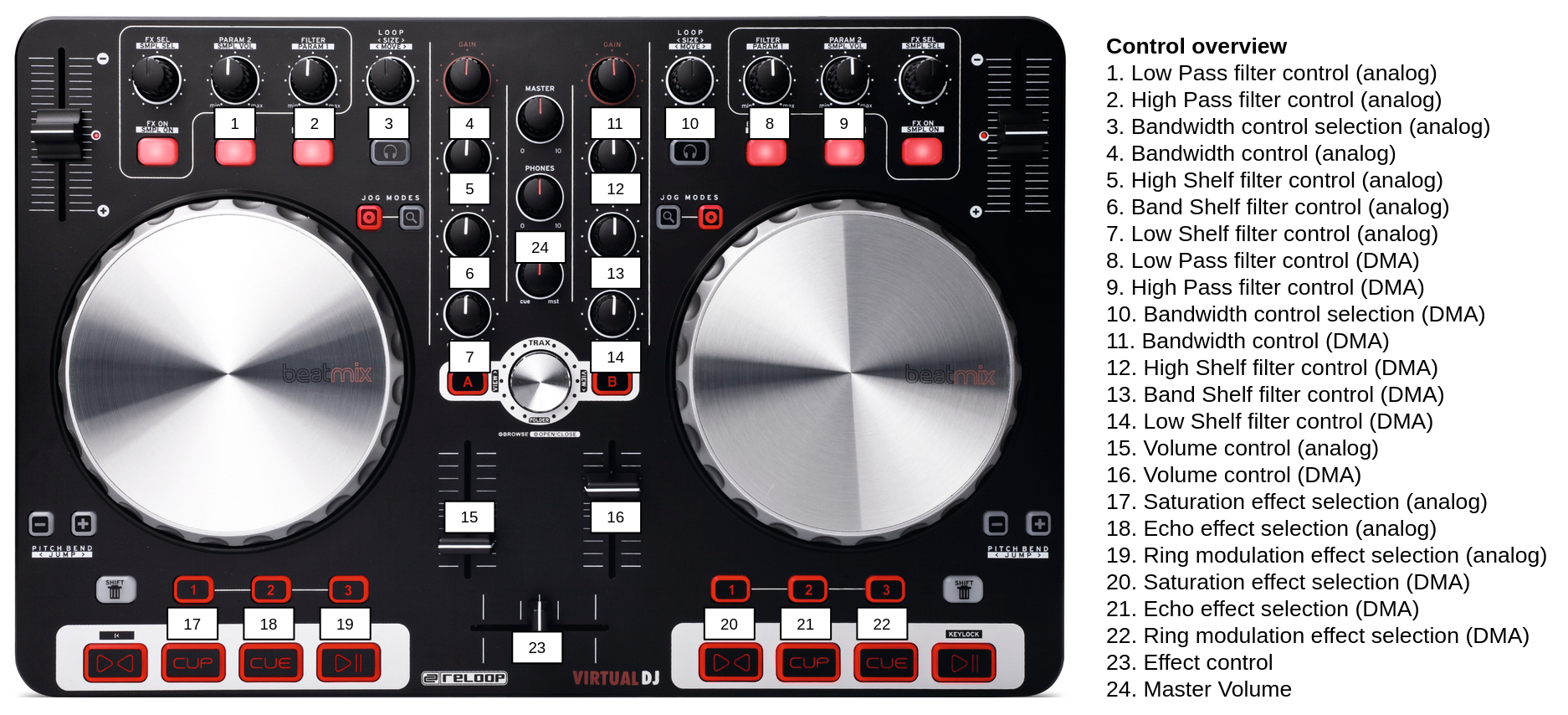
In our final project, we will use a Reloop BeatMix to send MIDI signals to control our signals. The MIDI port name of this device is Reloop BeatMix:Reloop BeatMix MIDI 1 24:0. Here you can find an overview of the Reloop BeatMix controls we use, the MIDI signals they send and how we will use them in our project:
-
Left linefader: [176, 55,
value]- 176 (Status Byte): Control Change on MIDI Channel 1
- 55 (Controller Number): Controller 55
value(Controller Value): Specifies the state of Controller 55, ranging from 0 to 127- Use in project: Volume control for analog signal
-
Right linefader: [177, 71,
value]- 176 (Status Byte): Control Change on MIDI Channel 2
- 55 (Controller Number): Controller 71
value(Controller Value): Specifies the state of Controller 71, ranging from 0 to 127- Use in project: Volume control for DMA signal
-
Left Effect Parameter 2 Dial (PARAM 2): [176, 48,
value]- 176 (Status Byte): Control Change on MIDI Channel 1
- 48 (Controller Number): Controller 48
value(Controller Value): Specifies the state of Controller 48, ranging from 0 to 127- Use in project: Lowpass filter control for analog signal
-
Left Filter Dial (FILTER): [176, 49,
value]- 176 (Status Byte): Control Change on MIDI Channel 1
- 49 (Controller Number): Controller 49
value(Controller Value): Specifies the state of Controller 49, ranging from 0 to 127- Use in project: Highpass filter control for analog signal
-
Right Filter Dial (FILTER): [177, 64,
value]- 177 (Status Byte): Control Change on MIDI Channel 2
- 64 (Controller Number): Controller 64
value(Controller Value): Specifies the state of Controller 64, ranging from 0 to 127- Use in project: Lowpass filter control for DMA signal
-
Right Effect Parameter 2 Dial (PARAM 2): [177, 65,
value]- 177 (Status Byte): Control Change on MIDI Channel 2
- 65 (Controller Number): Controller 65
value(Controller Value): Specifies the state of Controller 65, ranging from 0 to 127- Use in project: Highpass filter control for DMA signal
-
Left EQ Dial (HIGH): [176, 51,
value]- 176 (Status Byte): Control Change on MIDI Channel 1
- 51 (Controller Number): Controller 51
value(Controller Value): Specifies the state of Controller 51, ranging from 0 to 127- Use in project: High Shelf filter control for analog signal
-
Left EQ Dial (MID): [176, 52,
value]- 176 (Status Byte): Control Change on MIDI Channel 1
- 52 (Controller Number): Controller 52
value(Controller Value): Specifies the state of Controller 52, ranging from 0 to 127- Use in project: Band Shelf filter control for analog signal
-
Left EQ Dial (LOW): [176, 53,
value]- 176 (Status Byte): Control Change on MIDI Channel 1
- 53 (Controller Number): Controller 53
value(Controller Value): Specifies the state of Controller 53, ranging from 0 to 127- Use in project: Low Shelf filter control for analog signal
-
Left Loop Length Dial (LOOP < SIZE >): [144, 49,
value]- 144 (Status Byte): Note On message on MIDI Channel 1
- 49 (Note Number): Note 49
value(Velocity): Specifies the velocity of the note, with a value equal to 0 or 127, depending on depending on whether the dial is pressed or released- Use in project: Bandwidth control selection for analog shelving filters
-
Left Gain Dial: [176, 50,
value]- 176 (Status Byte): Control Change on MIDI Channel 1
- 50 (Controller Number): Controller 50
value(Controller Value): Specifies the state of Controller 50, ranging from 0 to 127- Use in project: Bandwith control for analog shelving filters, based on the bandwith selected with Note 49 on Channel 1
-
Right EQ Dial (HIGH): [177, 67,
value]- 177 (Status Byte): Control Change on MIDI Channel 2
- 67 (Controller Number): Controller 67
value(Controller Value): Specifies the state of Controller 67, ranging from 0 to 127- Use in project: High Shelf filter control for DMA signal
-
Right EQ Dial (MID): [177, 68,
value]- 177 (Status Byte): Control Change on MIDI Channel 2
- 68 (Controller Number): Controller 68
value(Controller Value): Specifies the state of Controller 68, ranging from 0 to 127- Use in project: Band Shelf filter control for DMA signal
-
Right EQ Dial (LOW): [177, 69,
value]- 177 (Status Byte): Control Change on MIDI Channel 2
- 69 (Controller Number): Controller 69
value(Controller Value): Specifies the state of Controller 69, ranging from 0 to 127- Use in project: Low Shelf filter control for DMA signal
-
Right Loop Length Dial (LOOP < SIZE >): [145, 49,
value]- 145 (Status Byte): Note On message on MIDI Channel 2
- 49 (Note Number): Note 49
value(Velocity): Specifies the velocity of the note, with a value equal to 0 or 127, depending on depending on whether the dial is pressed or released- Use in project: Bandwidth control selection for dma shelving filters
-
Right Gain Dial: [177, 66,
value]- 177 (Status Byte): Control Change on MIDI Channel 2
- 66 (Controller Number): Controller 66
value(Controller Value): Specifies the state of Controller 66, ranging from 0 to 127- Use in project: Bandwith control for DMA shelving filters, based on the bandwith selected with Note 49 on Channel 2
-
Left Hot Cue Button 1: [144, 41,
value]- 144 (Status Byte): Note On message on MIDI Channel 1
- 41 (Note Number): Note 41
value(Velocity): Specifies the velocity of the note, with a value equal to 0 or 127, depending on depending on whether the dial is pressed or released- Use in project: Saturation effect control selection for analog signal
-
Left Hot Cue Button 2: [144, 42,
value]- 144 (Status Byte): Note On message on MIDI Channel 1
- 42 (Note Number): Note 42
value(Velocity): Specifies the velocity of the note, with a value equal to 0 or 127, depending on depending on whether the dial is pressed or released- Use in project: Echo effect control selection for analog signal
-
Left Hot Cue Button 3: [144, 43,
value]- 144 (Status Byte): Note On message on MIDI Channel 1
- 43 (Note Number): Note 43
value(Velocity): Specifies the velocity of the note, with a value equal to 0 or 127, depending on depending on whether the dial is pressed or released- Use in project: Ring modulation effect control selection for analog signal
-
Right Hot Cue Button 1: [145, 41,
value]- 145 (Status Byte): Note On message on MIDI Channel 2
- 41 (Note Number): Note 41
value(Velocity): Specifies the velocity of the note, with a value equal to 0 or 127, depending on depending on whether the dial is pressed or released- Use in project: Saturation effect control selection for dma signal
-
Right Hot Cue Button 2: [145, 42,
value]- 145 (Status Byte): Note On message on MIDI Channel 2
- 42 (Note Number): Note 42
value(Velocity): Specifies the velocity of the note, with a value equal to 0 or 127, depending on depending on whether the dial is pressed or released- Use in project: Echo effect control selection for dma signal
-
Right Hot Cue Button 3: [145, 43,
value]- 145 (Status Byte): Note On message on MIDI Channel 2
- 43 (Note Number): Note 43
value(Velocity): Specifies the velocity of the note, with a value equal to 0 or 127, depending on depending on whether the dial is pressed or released- Use in project: Ring modulation effect control selection for dma signal
-
Horizontal Crossfader: [180, 83,
value]- 180 (Status Byte): Control Change on MIDI Channel 5
- 83 (Controller Number): Controller 83
value(Controller Value): Specifies the state of Controller 83, ranging from 0 to 127- Use in project: Effect control based on the effect selected with the Hot Cue Buttons
-
Headphones Volume Dial: [180, 81,
value]- 180 (Status Byte): Control Change on MIDI Channel 5
- 81 (Controller Number): Controller 81
value(Controller Value): Specifies the state of Controller 81, ranging from 0 to 127- Use in project: Master volume control
This gives us the following mapping on the Reloop BeatMix controller: